EC fan controller

Early stage of controller testing.
Description
I have prepared this project for one of my university courses, but I think it is worth sharing. If you are interested in controlling the speed of a fan or motor with an electronic commutator (EC) and you don't want to buy one, this might be for you.
This controller is powered from mains (110 V or 230 V AC) and is directly connected to the EC fan. My controller was designed to control Delta fan (GTW012FU604 to be specific).
This fan takes 10 V PWM as an input and it generates two pulses at each full rotation.
Designed controller displays desired speed, measured speed (in rotations per minute RPM) as well as duty cycle of output signal.
The microcontroller used is ATmega 328p, so it can be programmed as Arduino, with all the Libraries being easy to use.
What is EC motor anyway?
DC motors are very popular in our lives. They use set of windings (coils) on a rotating shaft and stationary magnets around the shaft. In order to keep that type of motor spinning in one direction we need to pass electric current in correct direction. The direction of current is controlled by a commutator which in DC motors is a mechanical part that uses a pair of brushless that touch the conductive part of the shaft (rotor). This mechanical commutation has the disadvantage of limiting the lifespan of the motor. AC motors on the other hand have simpler commutation since current changes its "direction" thanks to alternating current. This makes motor reliable but we have limited ability of controlling its rotations.
Electronic commutator uses an active rectifier to steer the direction of current for the motor. This is an efficient solution because all the power electronics is close the motor and it allows us for precise control. EC motor has advantages of DC motors, like ease of control and AC motor (or any brushless motor) like reliability. Because of the onboard electronics fan can also use hall sensors to detect the rotations of the rotor.
Thanks to its high efficiency EC fans can reduce electricity bills and because they can maintain efficiency across a wide RPMs spectrum they are often embedded in industrial applications.
Basic Specification
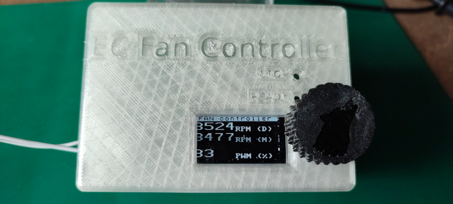
Assembled controller in 3D printed case.
- 1.4" OLED display
- Encoder for setting the speed, it also has start/stop switch
- Two LEDs as indication of fan status
- Dimensions: 92x65x45 mm
- High isolation between fan connector and electronics
- Powered from mains.
- ATmega 328p mcu, compatible with Arduino
- ICSP and TX/RX pins for programming and debugging
- EMI suppression and safety circuitry on the AC side of the PCB
- Reverse voltage protection
- Arduino compatible, uses high level libraries
- Easy to program your own frequencies
- 3D model of case and knob that can be printed

Back of the PCB is front of the device.
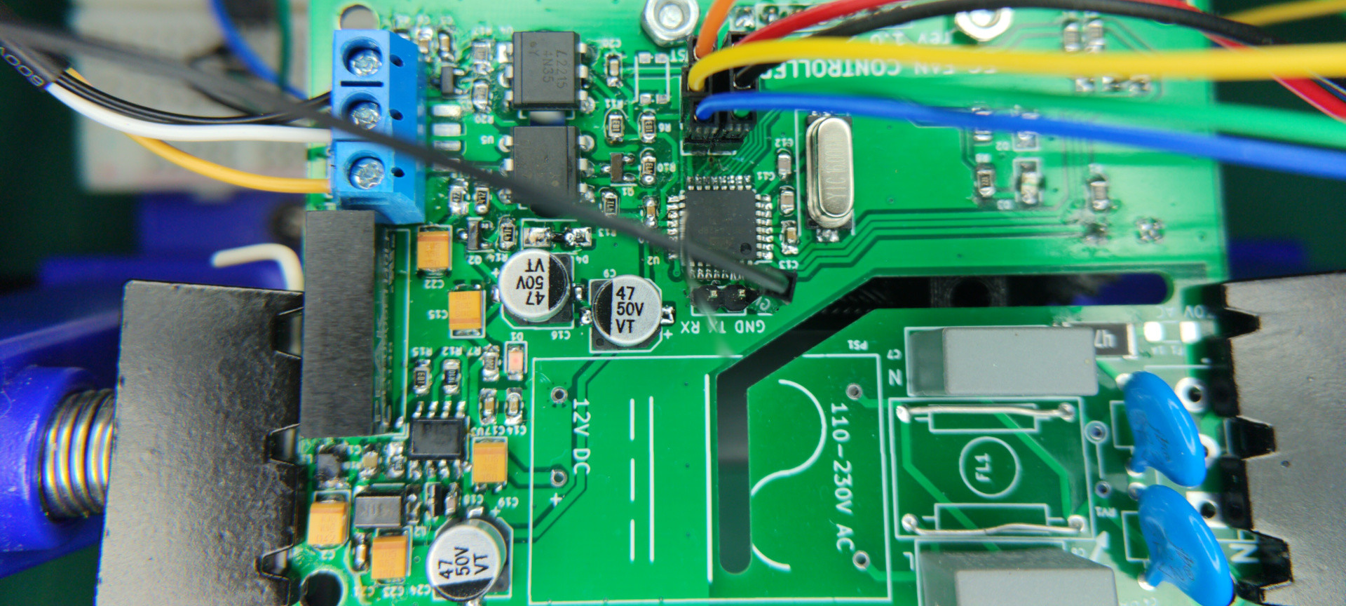
Front of the PCB contains all SMD parts
Theory of operation

Block diagram, dashed line marks the controller.
Used fan as is typical for industrial application uses 10Vpp PWM signal as an input, changing duty cycle
changes the speed from 5% dt required for the fan to start and 95% to reach full RPM (4100). Fan also
outputs FG signal which sends two pulses for each rotation of a propeller.
This model also accepts 0-10V DC input as a speed control with hysteresis curve and linear slope but we will
use PWM for control.
Power rails
Controller is powered from 230 V AC mains, meaning that some safety must be a concern during a design
stage. At the input 1 A slow blow fuse is installed together with 47 Ω resistor and parallel mov to clamp down
spikes. Two Y class capacitors are connected to the earth terminal which is connected to a common ground.
There is also a common mode filter for EMI compliance with two 150 nF X class capacitors on each side.
Part of the schematic that describes the 12 V.
Next a module AC-DC (PPME02) converter is used for supplying 12 V DC. This rail is then filtered
with three capacitors and all other rails are derived from it. It is worth to mention that PPME02 provides
galvanic isolation of 4 kV, efficiency of 76% and maximal current of 167 mA.
The 5 V rail that mainly powers the microcontroller and its peripherals is created with DC-DC step down
converter based on MC34063AD. Another 5 V (denoted with power flag
5 Vp) rail is derived using isolated DC-DC converter, it is used for input from the fan (generating the FG
signal). In case of this rail an additional resistor (R5 ) is put in place
as a load since data sheet claims correct operation above certain load for this converter.
Finally 10V rail is non isolated galvanically and is used to create 10 Vpp to swing the PWM output. Not
a lot of current is necessary from it and because of less typical value it is created using Zener diode and a
transistor regulator.
Input and output conditioning
Since controller is intended to work in industrial application and be powered from mains some form of I/O
isolation is required both for safety of the user but also for the protection of vulnerable microcontroller.
Output from the microcontroller PWM pin goes to a NPN transistor through a 47 K resistor. Role of the transistor is to turn on the
LED diode inside optocoupler (4N35). The driving transistor is here so that we can use higher current for the
diode allowing for faster switching time, it also provides layer of protection for the pin which has small limit
of current per port. Anode of the diode connects by resistor to a common 5V rail which is also powering the
microcontroller. The other side of output opto coupler is a photosensitive transistor which collector connects
to a 10 V rail derived from 12 V by the use of Zener-PNP regulator. This solution does not provide full
isolation for the power supply rails but it protects the microcontroller. We don’t expect anything harmful
on this line since it is the output of our board. The pull up resistor is a 10 K and emitter of transistor connects
to the ground. As an additional protection for the board a spark gap is placed close to the output terminal to
provide ESD protection.
The input signal from the fan is a pulse train with two pulses for each rotation. Maximum speed is 4100
RPM so 8200 pulses per minute which equates to 137 Hz. This frequency is in range of most optocouplers
in DIP packages. We don’t need any squarer to improve the signal.
From the datasheet we can see that the FG signal is created by a common emitter transistor inside the
fan that requires external pull up resistor. Also from the sixth page of the datasheet we can read
Rg (on our board R19 ) is 4.7 K resistor and it connects 5 V p isolated rail to a PNP transistor
that drives LED in optocoupler. The other side of optocoupler (collector of photo-transistor) is pulled up to
common 5 V. This is how FG signal gets to microcontroller.
Microcontroller
The microcontroller is ATmega 328p, it was chosen because of the available Arduino libraries and the fact
that is even now easy available on the market and has enough resources and timers for our purpose. This
Schematic

GitHub source code and gerbers
You can visit my GitHub repository in order to download Gerber, KiCad files and code that you can flash to the microcontroller.
Link (sorry, not quite ready to publish it, email me if you need something)
Measurements
Two voltage rails that are created using custom circuitry (ie. not converter modules) are 5 V digital rail and 10 V. That is why special attention during the testing was put on measuring those rails.
The non isolated 5 V rail that powers the microcontroller is created using MC34063, I have tested the output of this Buck converter for 10 minutes and it maintained a stable voltage of: 4.6752 V. This is acceptable value since Atmega 328p accepts up to 5.5 V. Since we definitely don’t want to have 12 V
on the microcontroller power rail I have also measured the output of the 5 V rail as the device is powered
on (all capacitors discharged) using an oscilloscope.

Signal from the fan (FG) received on the interrupt pin at maximal RPM.

Output from the controller, duty cycle (% dt) sets the RPM

5 V rail shows no overshoot

Plot of the RPM measured by the controller vs desired RPM (datasheet value)