Forte: 600 W LDMOS RF Amplifier

Working Forte 600 amplifier in my shack.
Description
Forte 600 is an open hardware and source project that aims to create a 600 W RF amplifier based on MRF300 LDMOS transistors. This proejct covers not only the amplifier board with transistors but also the low pass filter section, controller, front panel and TX/RX relay board.
This amplifier is designed to cover amateur bands from 1.8 to 30 MHz with full CW output power of 600 W and 50 MHz band (6m) with at least 3 dB below the full output power. Similarly to most of the modern constructions of LDMOS amplifiers it uses TLT (transmission line transformer) allowing for broad band operation. Amplifier has a power supply integrated in its case.
What differentiates the Forte 600 from other amplifiers?
- All the schematics and PCB files are avaiable for free.
- Throught harmonics and linearity tests.
- More complex low noise and temperature characterized gate bias network.
- Multiple directional couplers in order to detect fault in LPF section.
- STM32 microcontroller running real time operating system. Responsive interface and fast fault handling.

Forte amplifier under test
Basic Specification
- CW Peak: 600 W (from 5.4 to 18.2 MHz, no LPF)
- Peak power added efficiency (PAE): 71.8% at 14.15 MHz
- More than 500 W CW from 3.6 to 30 MHz with PAE ≥ 56.7%
- 400 W at 1.8 MHz with 48.4% PAE
- Gain ≥ 17 dB (max input power)
- Worst case harmonic suppression: 53.89 dBc with added LPFs
- No tuning required, automatic band switching
- Multi level fail-safe protections, digital power, SWR, drain current, temperature display
- STM32F103 microcontroller with FreeRTOS for responsive operation
In depth docummentation
My master thesis describes development process, theory of operation and most importantly - measurements of this amplifier.
You can read it here:
Forte 600 docummentation
Based on my measurements I have also published a paper in Radioengineering journal:
Optimizing Shortwave Wideband RF Amplifier: Study of
Transmission Line Transformer Construction Methods.
PCBs and assembly photos

Power deck

Low pass filters

Controller PCB
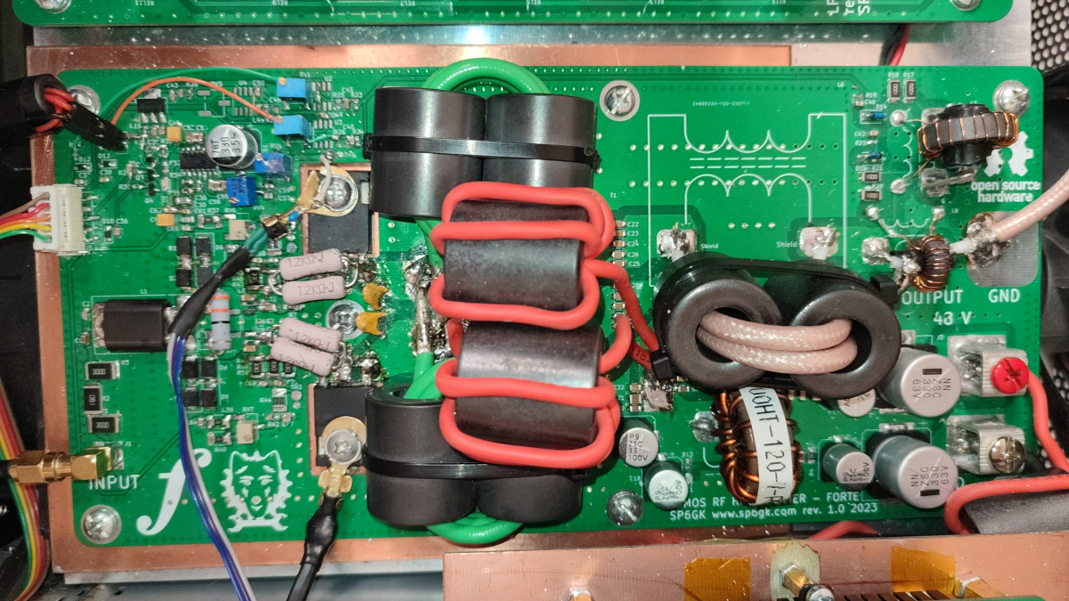
Deck - PCB with power transistors
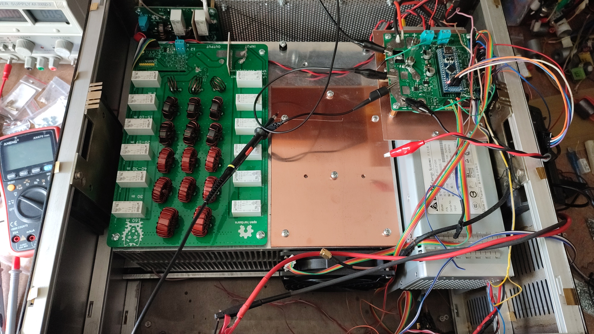
Heat spreader
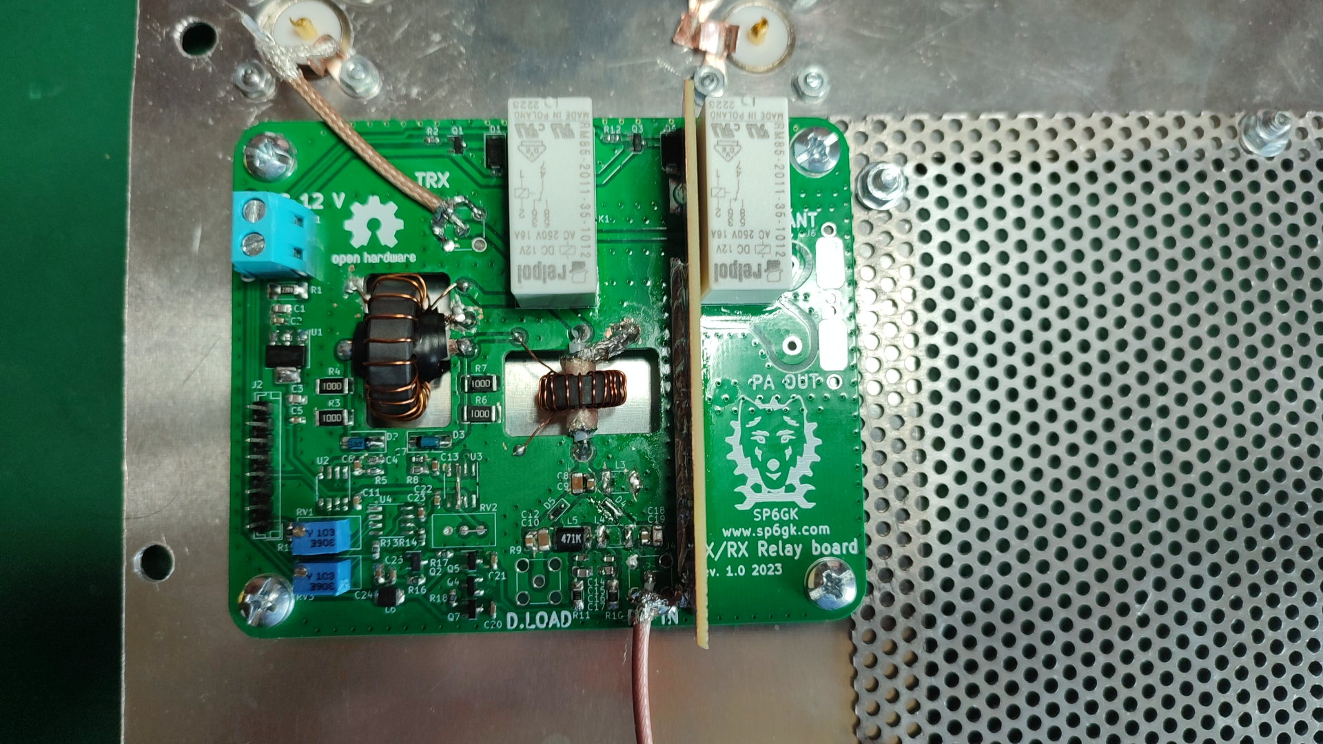
TX/RX relay and input protection
Schematics
RF deck schematics: PDF
LDMOS amplifier controller scehmatics: PDF
Low pass filters schematic: PDF
Transmit and receive relay and input protection schematic: PDF
Measurements
Below figures show maximum output power, gain and efficiency across HF bands. These results are for the PA deck with no low pass filter.

Maximum output power and gain

Power added efficiency across HF spectrum

Gain and output power for increasing input at 14.15 MHz
GitHub source code and gerbers
You can visit my GitHub repository in order to download Gerber, KiCad files and code that you can flash to the microcontroller.
KiCad project, BOM, schematics of PA board
Software (v1) I am currently working on v2 based on STM32F411.
Note: Controller PCB project is avaiable upon email request, however I am not happy with how it turned out. New revision is on the roadmap but don't expect it soon.