Together We Can Do It!

This page is ad-free, instead of donating to me please consider supporting the Ukraine.

United24.ua

Home About Changelog my QRZ.com YouTube

ADF4351 based local oscillator module

Description

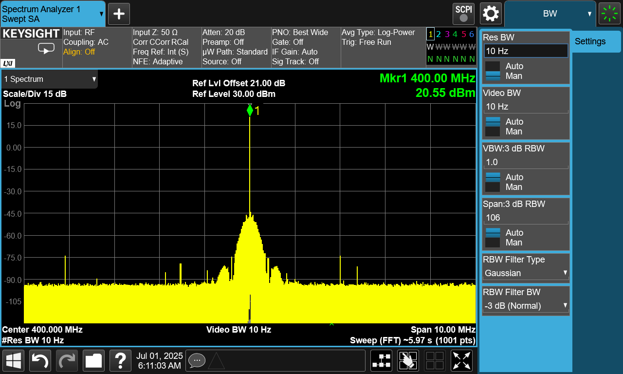
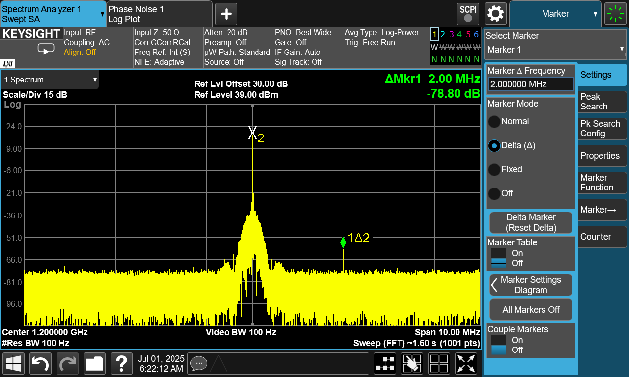
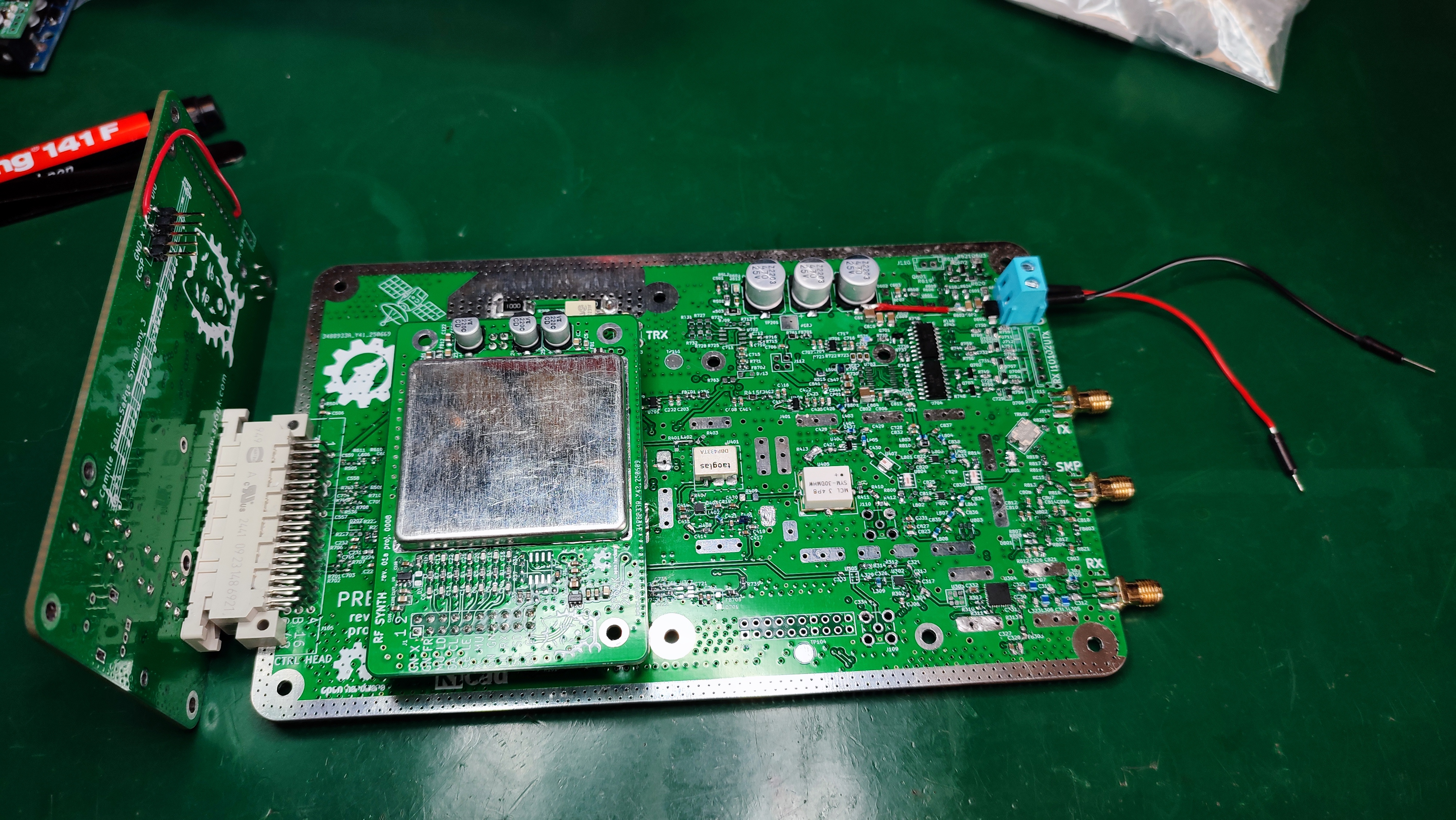
This PCB is designed as a drop in module for any design that requires a high quality RF CW signal with at least 16 dBm of power. This is a common requirement for passive RF mixers, which can offer very good linearity (high IP3) when driven by a relatively high power local oscillator signal. Besides delivering 13–20 dBm, the signal should also contain as few harmonics as possible. The performance of the local oscillator affects the entire signal path in a heterodyne system therefore, it should be stable and exhibit low phase noise and contain little to no spurious emissions.

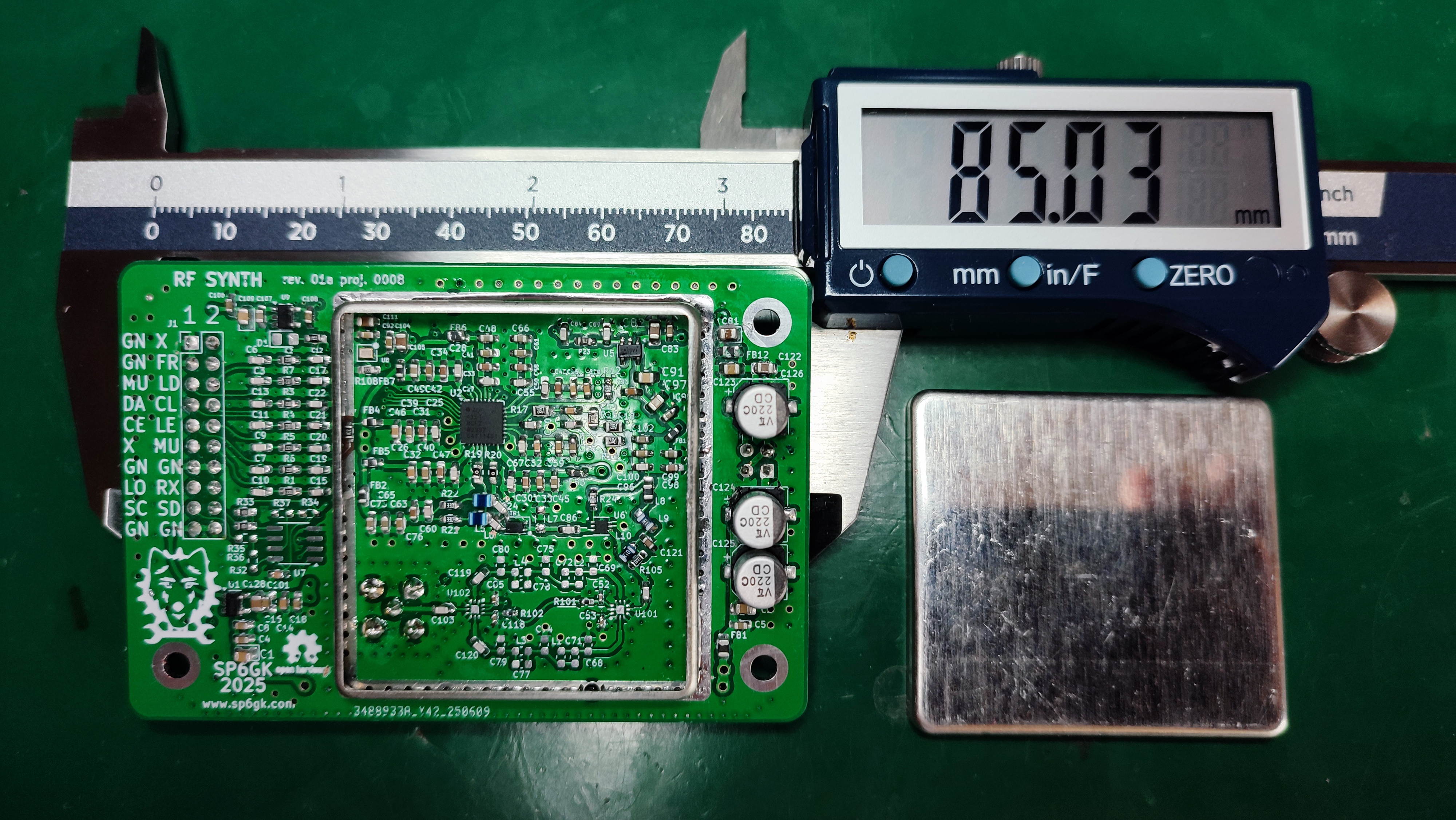
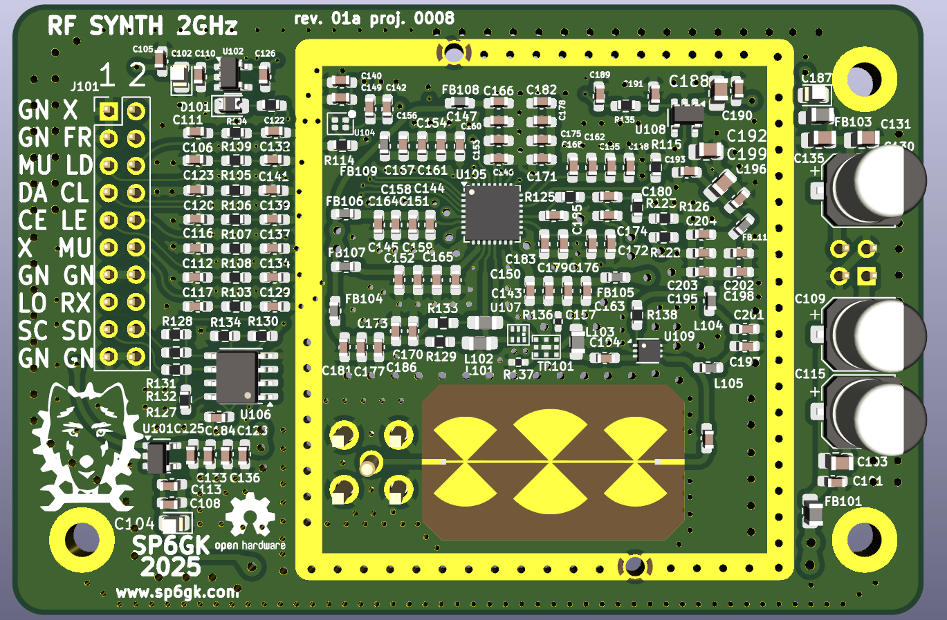
This module was developed as part of the Presto HF to QO 100 (S band up-link) transverter project, but thanks to its easy mounting scheme it can be used as a drop in component in many other projects. Because of the high quality components used and rigorous filtering of every stage, it should outperform most inexpensive evaluation boards available for this PLL. The shield used is MS483-10.

Specification

  • Optimal frequency range: 400 MHz to 900 MHz (can be optimized for other frequencies).
  • Output power: 20 dBm into a 50 Ω load across the optimal frequency range.
  • More than 17 dBm between 100 MHz and 2.4 GHz.
  • Phase noise: −89 dBc/Hz at 100 Hz offset, −97 dBc/Hz at 10 kHz offset (at 400 MHz CW).
  • 0.5 ppm VCTCXO reference with a 12-bit DAC for digital tuning.
  • Two selectable low-pass filters to minimize harmonics.
  • Fractional-N PLL (ADF4351).
  • Size: 85 × 57 mm.
  • Recommended input voltage: 3.6 V (5.5 V absolute maximum) and 5.5 V for the PA stage.
  • Current consumption < 250 mA (TBD), can be minimized by disabling output.
  • On board EEPROM for calibration retention.

Applications

  • Test and measurement equipment
  • VHF/UHF communication
  • Amateur radio equipment
  • Backhaul network

Source

You can find all the files and documentation in this GitHub repository: Link.
I have tested my board with STM32 driver written by KB3GTN on STM32F407 discovery.


Measurements

I had the opportunity to use Keysight’s CXA spectrum analyzer (N9000B) with the phase-noise measurement option.
Deck - PCB with power transistors
Phase noise at 1.2 GHz
LPF PCB
Phase noise at 400 MHz
100MHz
Phase noise at 100 MHz


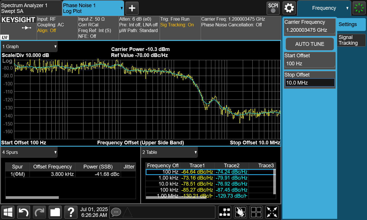
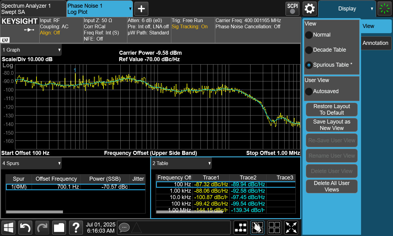
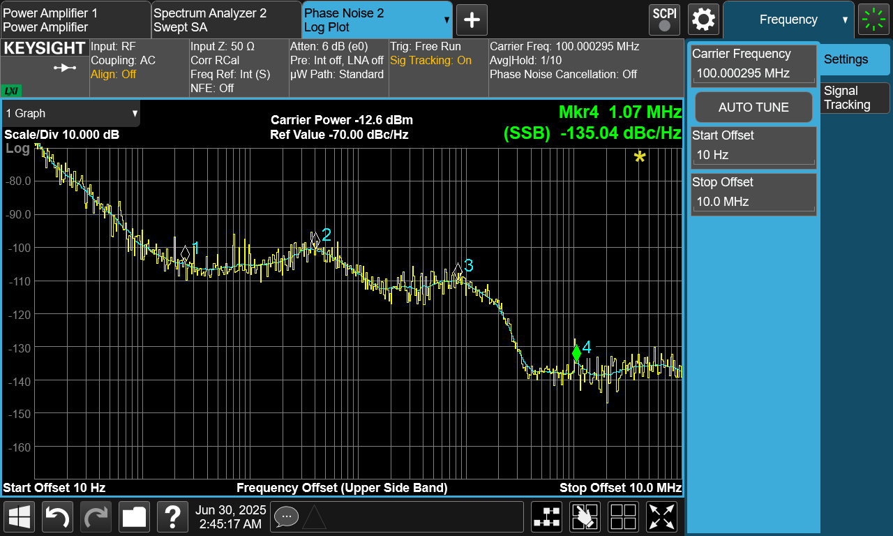
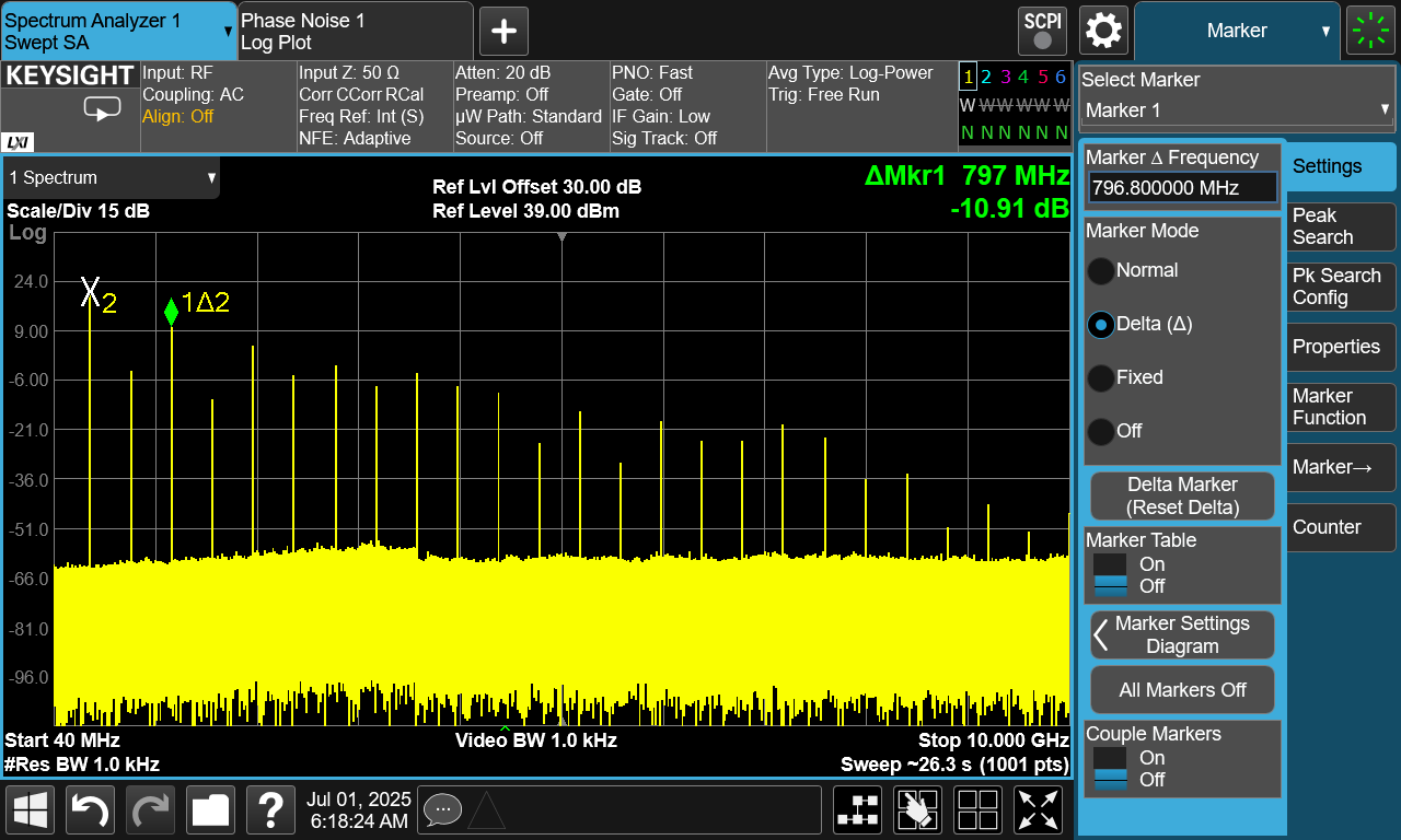
The ADF4351 can operate up to 4.4 GHz however, to provide a flat response and sufficient output power, the circuitry following the PLL output has a narrower bandwidth. My main goal was to cover 400–800 MHz in the transverter: 430 MHz is the IF frequency, ~400 MHz is used as the first LO in transmit mode, and ~700 MHz is used in receive mode to down convert the signal from the LNB. The limiting factors are:
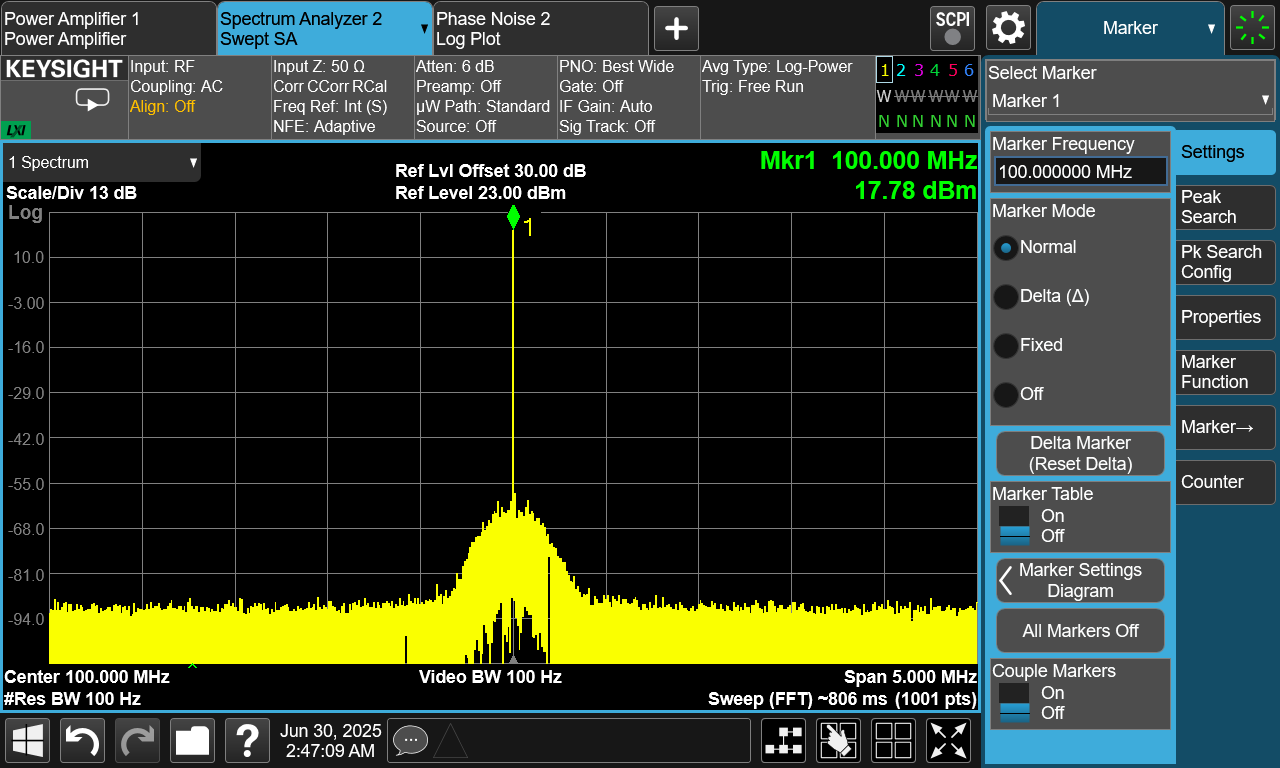
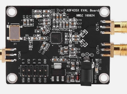
  • The balun (the main reason for the optimal frequency range).
  • The power amplifier (rated for 150 MHz to 5.8 GHz, I recommend adjusting the bias-tee section, lower frequencies can also be covered by swapping the amplifier to a GRF4003).
  • The low-pass filters (the current revision uses discrete LC elements, I also plan a revision with a single microstrip filter).
At the moment of the measurements I have not installed the LC elements for the filters in order to observe the output directly from the power amplifier.
Output 400 MHz
Output at 400 MHz
1200MHz
Output at 1.2 GHz
400MHz harmonics
Harmonics at 400 MHz

100 MHz (wide span)
Output at 100 MHz (50 MHz span)
100MHz (narrow span)
Output at 100 MHz (5 MHz span)
LO module mounted in Presto transverter


ADF4351 eval module from Ebay (for comparison)

I didn’t have enough time to measure a cheap module from eBay using the Keysight equipment, but I did make some measurements with my Rigol DSA815 (an instrument that, mind you, is about 40 times cheaper). This module uses an AMS-1117 regulator, which has poorer PSRR compared to the NCP-163 used in my module. The cheap module also relies on a 50 ppm 25 MHz crystal and has less decoupling/filtering on the power rails. These cost-cutting choices result in noticeably worse phase noise. Fun fact: with a low enough RBW, you can even see 50 Hz tones coupling in from the mains. Notice that this module also delivers much lower output power.
Ebay module
Tested module from Ebay
100MHz (narrow span)
Output at 100 MHz (5 MHz span)
Output from generic ADF4351 module
433 MHz output from a generic ADF4351 module (1 MHz span)

Evaluation of LPFs

In progress

Schematic


Radios

Contact me

sp6gk 'at' protonmail.com

Restored tube radio

Here is a demonstration of restored radio from 1938.

Band conditions

Check out my RF amplifiers with distributed matching networks

2.4 GHz PA

Almost assembled fully home made 2.4 GHz power amplifier on LDMOS transistor.


2400 MHz hairpin v1

1.25 GHz small signal amplifier with open stub matching. Active element is BFP420 BJT.


Flag counter

Flag Counter