

This 92x85mm board allows you to plug up to 264 switches and three analog inputs
that controls your virtual theatre organ software.
This switches and inputs may include:
The device scans a matrix of switches so there are no 264 pairs of wires. Matrix consists of 24 columns and 6+5 rows (6 rows dedicated to stops and 5 to pistons and effects). Generally you get 24 times 11 inputs (264 total) but software that I provide has initially been configured to use the 6 stops rows. Because MIDI command change messages have control values from 0 to 127 to get more stops than 128 you need also assign different control data. Miditizer uses control value to address stop and two different control data to turn them on or off.
If you are new to MIDI, consider reading my tutorial on VTPO where I explain my experience with integrating this board to work with Miditizer.
If you want to build an organ which has up to 128 tabs your job will be much easier. Above 128 you need to use different data values in a MIDI control change message. In my code I use mostly 80 and 81 for one set of 128 tabs and 82/83 for another set.
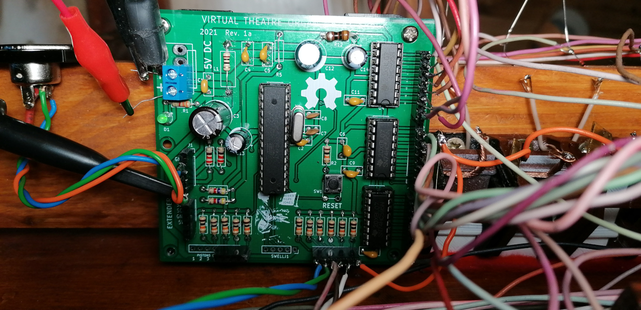
Programming itself is easy because the board uses ATmega328p and I provide an Arduino code so you can program it just like Arduino Uno. Code uses high level libraries for shift registers and MIDI so it is quite easy to understand and modify.

")
For the switches the device uses a method of scanning the matrix, it is also known as multiplexing since the amount of wires is greatly reduced. The board uses three 8 bit shift registers: 74HC595. Each of those three integrated circuits has 8 outputs, they are daisy chained, meaning they are in series and in total they offer 24 outputs that can be turned on or off by the microcontroller. Notice that these can serve only as output with state high or low. Further they will be refereed as columns (24 columns)
Matrix just like in mathematics consists of rows and columns, just imagine rectangular grid with vertical lines being rows and horizontal lines being columns, intersection points are the switches.
Now the rows, they are inputs on the microcontroller. The microcontroller sweeps the outputs of shift registers in a loop from 1 to 24. At each iteration output of shift registers (rows) is known and the microcontroller reads the columns. Then using the knowledge about two it is known which switch in checked column is switched.
Notice that matrix is a bounded array with dimensions rows x columns each row can check a maximum of 24 columns.
There are two problems with this solution. First one easy to solve is that with multiple switches in closed position (conducting) which is normal for an organ (multiple stops pulled out) it would be possible for a signal to flow from one row through a few switches to incorrect rows. Solution is to use a signal diode (1N4148 will work) facing the row for every switch, so you need as many diodes as you have switches. Fortunately those diodes are very cheap.
You might also notice another problem, we are not checking all switches at once. There is some delay with only one column being checked at a time. Generally for this amount of tabs this is not a problem since the microcontroller is quite fast and you won't notice a delay in real life.
On the software side, in the microcontroller's loop you need to remove comment before expresion(); function call (remove // before it) to enable swell pedals readout.
In a main loop there is an inner loop which goes through 24 columns. On each iteration this loop sets output of all columns to low and then sets one of the rows to high (according to what iteration is now executed). Rows are then read, at this point we know the state of which column is checked and what rows are set to high. We can use conditionals (if) to check whether switches have been switched in and then if they were combine that information with row number to get value from MIDiMap, this assigns values from 0 to 127 which are passed to MIDI function which uses serial of Arduino (ATmega 328p) to send a control change message. Inside this function we also pass a data value which can be used to expand the organ to more than 128 tabs.
Notice that code is quite repetitive and easy to scale.
Second major conditional checks whether any switches were released (turned off). The only difference is that different data values are send (not the value from the map, they stay the same since they correspond to rank or effect), this data corresponds to data in Miditizer that turns off the tab.


You can visit my GitHub in order to download Gerber, KiCad files and code that you can flash to the microcontroller. Gerbers can be used to order PCB from sites like JLPCB for further assembly. The current revision does not have an ICSP connector. I recommend soldering a DIP-28 socket to the board and uploading my code to Arduino Uno (can be a clone but must come with DIP package ATmega) and then remove the ATmega from Uno and put it in the socket.
Beside electronics I have also designed a bracket that holds the PCB and can be screwed to a side wall of a console and a DIN-5 socket bracket which gives you the option to mount a MIDI out connector. Both can be 3D printed

sp6gk 'at' protonmail.com
Here is demonstration of restored radio from 1938.