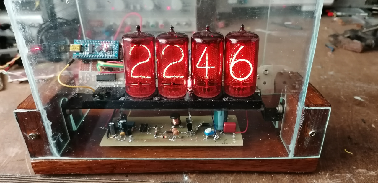


This simple Nixie clock was made over the weekend during pandemic only from parts that I have found in my lab. I strongly oppose disassembling vintage measurement equipment just to get Nixie tubes, but I got two sets of Z566M and electronics to drive them from a company that is doing electronics recycling. Unfortunately they did not save the rest of the meter (it was probably an old Meratronik V553 multimeter). So I have decided to reuse them.
This project focuses more on driving the Nixie tubes (HV and Arduino code) rather than creating something useful since I did not have an RTC IC at the moment so the Arduino has to calculate time, it will not provide accurate timing after many cycles.
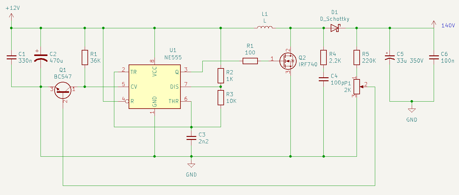
The power supply is a boost converter that converts the 12V to a 145V (under load). With no load the power supply generates about 170V. This is enough to light up the Z566M.
Mosfet is driven by NE55, the duty cycle can be changed via potentiometer that is in a feedback loop. The switching frequency is approximately 35KHz. As for a PCB it was my very early attempt at etching PCb at home, it's not perfect but it works.
The prototyping board on the left side has pin-headers for Arduino Nano board and two pin expanders ICs: PCF8574 on I2C interface. Those expanders provide 16 pins that serve as an outputs and they control four 74141 decoder IC.
The 74141 IC is an ABCD to 0-9 decoder that was designed to directly drive Nixie tubes. The ABCD gives 4 bits, one can check the truth table in a data sheet to see what combination is necessary for enabling specific digits.
The decoder ICs are on the same PCB as the Nixie tubes themselves, the ABCD inputs are connected by wires to the prototyping board and to the pin expanders.
In the software part I mainly wanted to exercise driving the tubes as a display so I wrote a function that takes the position (which digit to write) and actual number from 0 to 9. There is also a function that counts the time and splits the time into digits. The clock sends also current time over serial port.
Here is a schematic of a step up converter based on NE555. I also attached a PCB layout, it's not a good design (long traces) but it was a good exercise for home etching a PCB.
The inductor should be around 470uH, you can play around with a value of c3 (2.2n).

