

This project started as my engineering thesis. The idea is to develop a hardware-based SSB transmitter using modern test equipment to test the methods presented over the years by the amateur radio community. Adagio is a slow tempo in music, and this project is indeed slow compared to other projects, but it demonstrates methods of calculation, construction, and evaluation at every stage. Hence, the tempo of physical development is rather slow.
This project has shown that special care should be put into the construction of a crystal ladder filter, a step that seems to be sometimes poorly explained. Special attention to that section will be given in a separate article.


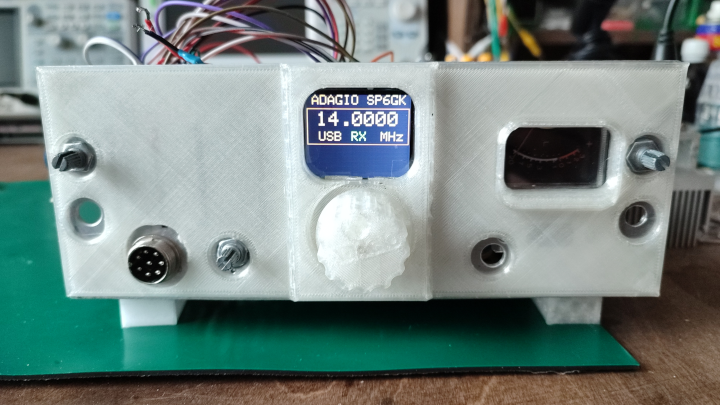
The goal of this thesis was to design a hardware-based single sideband (SSB) transmitter, intended for the 20 m amateur radio band (14.0-14.35 MHz). This frequency range places the transmitter within the shortwave spectrum, a spectrum actively utilized by government, military, and amateur radio operators. Additionally, the chosen frequency is in proximity to the ISM (Industrial, Scientific, Medical) band. SSB modulation in the shortwave spectrum typically operates within a limited bandwidth of 2.7 KHz. To achieve such a narrow transmission window, a filter method for SSB excitation was selected. The objective was to suppress the carrier by more than 50 dB, and to adhere to ITU (International Telecommunication Union) legal regulations. Furthermore, the thesis aimed to investigate and compare RF design methods and optimization techniques developed by the amateur radio community.
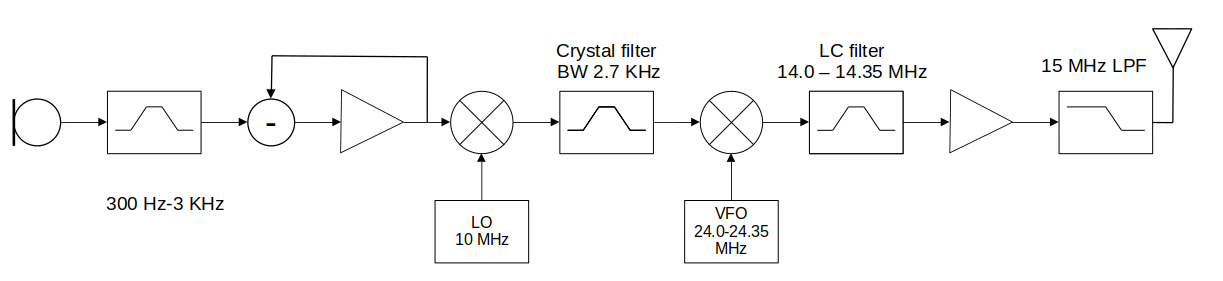
The first section of the thesis introduces the concept of double sideband (DSB) modulation with a suppressed carrier through an analysis of the Gilbert cell. A comparative study of two widely used active balanced mixers was conducted, focusing on the spurious free dynamic range (SFDR) and carrier suppression. The simpler NE602 circuit demonstrated 44 dB of carrier suppression and SFDR of 30 dB, representing an average performance. In contrast, the more complex MC1496 achieved a superior 52 dB of carrier suppression and SFDR exceeding 40 dB. Chosen intermittent frequency (IF) of the transmitter was 10 MHz.


To achieve a highly selective IF filter, common 10 MHz crystal resonators were used in a ladder configuration. This type of crystal filter requires precisely matched crystals with known motional parameters of series L, R, and C components, which are typically not provided in data sheets. Two methods of indirect measurement were compared. The first method involved measuring the S21 characteristics using a spectrum analyzer and was based on the frequency of series and parallel resonances. The second method, known as the G3UUR method, utilized a perturbation, noting changes in the frequency of oscillation. Both methods facilitated the determination of motional C and L parameters within the range of tens of fF and mH. In the series and parallel method, the Equivalent Series Resistance (ESR) and Q factor were also estimated for the selected crystals. Simulation results indicated that a minimum of six crystals was necessary to meet the attenuation slope recommended by the ITU. However, in the final design, only four crystals were used. The achieved attenuation slope was 26 dB/KHz on the lower side and 37 dB/KHz on the upper side. This closely matched the simulated filter, which achieved 23 dB/KHz and 32 dB/KHz for the same number of crystals, validating the effectiveness of the employed methods.


In the next stage, up-conversion was employed using a high side local oscillator, so that the steeper side of the filter rejects the opposite sideband and mirrors the spectrum to achieve the upper sideband at the output. This conversion technique was made possible through the use of DDS (Direct Digital Synthesis). The obtained SSB signal underwent further filtration using a double tuned circuit before being passed to a linear amplifier. To minimize costs, an investigation into the use of inexpensive IRF510 MOSFETs was conducted. In a push-pull configuration, a maximum output power of 44 dBm into a 50 Ω load was observed with a 28 V DC supply. Additionally, a low-pass filter was developed to attenuate harmonics by at least 55 dB below the fundamental tone signal.


In conclusion, this work provides valuable data for constructing hardware defined IF stages for RF receivers and transmitters. The study delves into various signal path design methods and optimization techniques developed by the amateur radio community, demonstrating their effectiveness. Further research might focus on using the designed RF chain in order to improve the performance of software defined radio (SDR) in the mixed architecture, where hardware based RF front end and IF provide good selectivity and Zero-IF SDR adds flexibility of digital signal processing (DSP).
Tip: you can press down arrow in the upper right corner of the embedded documment in order to download it.

sp6gk 'at' protonmail.com
Here is demonstration of a restored radio from 1938.